ReThink Construction

Sobha Lightweight Modular System

Stage 2 summary. Sign in to continue.

Stage 2 Concept Feasibility

Sobha Lightweight Modular System

An interactive summary of the Concept Feasibility Report (RC/SOBHA/S2/002 V2.4) and the Development Options companion paper (RC/SOBHA/S2/003 V2.4).

The verdict: the concept was calculated as viable to thirteen storeys on Sobha's own sections and gauges, exactly as provided. The route to twenty storeys was set out, every issue identified was mapped to solutions, and the system was assessed as sufficiently developed to proceed to prototype.
13
storeys, calculated as provided
20
storeys via the doubled post provision
5x
stiffness from doubling beam depth, vs 1.7x from full gauge range
8
issues identified, each mapped to solutions
~16t
module lifting weight, fitted out

The concept, as provided

Stage 2 examined the concept using Sobha's own proposed sections and gauges, without substitution.

150 x 75 posts

Toe to toe compounded C sections at gauges of 6, 8, 10 and 12mm, 390 N/mm². One profile serves corner and intermediate positions, varied by gauge, layered heaviest at the base.

200mm side beams

200 x 120 C sections, floor and ceiling. A shallow beam holds the floor to floor dimension down, a deliberate and well judged choice.

Male / female corner block

The module to module connection, locator and compression path. Reviewed for tolerance, manufacture and value engineering exposure.

MD60 composite deck

130mm overall depth spanning the 3.8m module width directly between the side beams, with no joists. The validated basis of the calculations.

From the same starting section, depth beats gauge start200 x 61.2x200 x 81.4x200 x 101.6x200 x 121.7x200 x 145.1x400 x 67.8x400 x 10 Stiffness Iₓ in cm⁴, from the calculation package. The full gauge range buys 1.7x; doubling the depth buys about five times at the same gauge.
Beam stiffness from the same starting section, the 200 x 6 side beam. Values from calculation package 26025.
The 150mm post in the 100mm wall, in plan wall zone, around 100mm 150 deep post projects ~50mm into the room 150 x 75 toe to toe pair room side
The unavoidable consequence of a 150mm post in a 100mm wall: an approximately 50mm projection into the room. Issue 2, with four solutions mapped.

The heart of it: four connected issues

The issues are not a list, they are a chain. Each one follows from the last, and the tempting shortcut at the end reopens the ones before it. These are the constraints the options have to work against.

Lever 1: depth

Deepen the beam and the posts fall away. Five times the stiffness for one move, against 1.7x for the whole gauge range.

Lever 2: arrangement and gauge

Place the posts where the plan can absorb them, and match the gauge to the position. The calculated mid span case bounds every pair arrangement.

Lever 3: control tolerance once

Set every node in the adjustable jig, in length and width, so each module leaves the bed to the same master datum.

Lever 4: lighten the floor

A dry build up cuts the floor dead load by roughly two thirds, easing every beam and post argument before any section changes.
Height: thirteen now, the route to twenty

Toggle between the two states. The calculations show the module standing to thirteen storeys with two intermediate posts, toe to toe at mid span, the hardest condition any support line can face. That case bounds every arrangement keeping the posts as pairs, and twenty storeys is reached by doubling the provision to a pair at each of two positions.

12mm 10mm 8mm 6mm

Thirteen storeys, as provided

Two intermediate posts, toe to toe at mid span, carry the full tributary load on one line. Height is delivered by layering the post gauge, heaviest at the base where the load accumulates, lightest at the top. Calculated with useful margin in every gauge band. Lateral stability within the stack comes from the flag plate moment connections and diaphragm action, wind checked as a stack to 34.2m under EN 1991-1-4. For the UAE deployment the design basis carries lateral demand at building scale on concrete cores, built first with the modules tying in at each level.

This concentrated arrangement is the conservative baseline: no support line in any other arrangement carries more than this checked case.
Thirteen storeys: two posts, toe to toe at mid span. The calculated case that bounds the rest. Twenty storeys: the provision doubled to a pair at each of two positions.
Each pair in the doubled arrangement carries well below what the mid span pair was checked for. Spreading single posts is the further refinement, with the gauge matched to each position.

The full issue register

The complete register from the feasibility report: eight issues, each mapped to its alternative solutions. Click any issue to expand.

Solutions for Sobha to review

The companion paper gathers the solutions explored during Stage 2, each tagged to the issue it resolves and honest about its trade. These are the things Sobha can review against the chain above. Click a card to expand.

Click any card for the detail behind it.

Engineering the corner

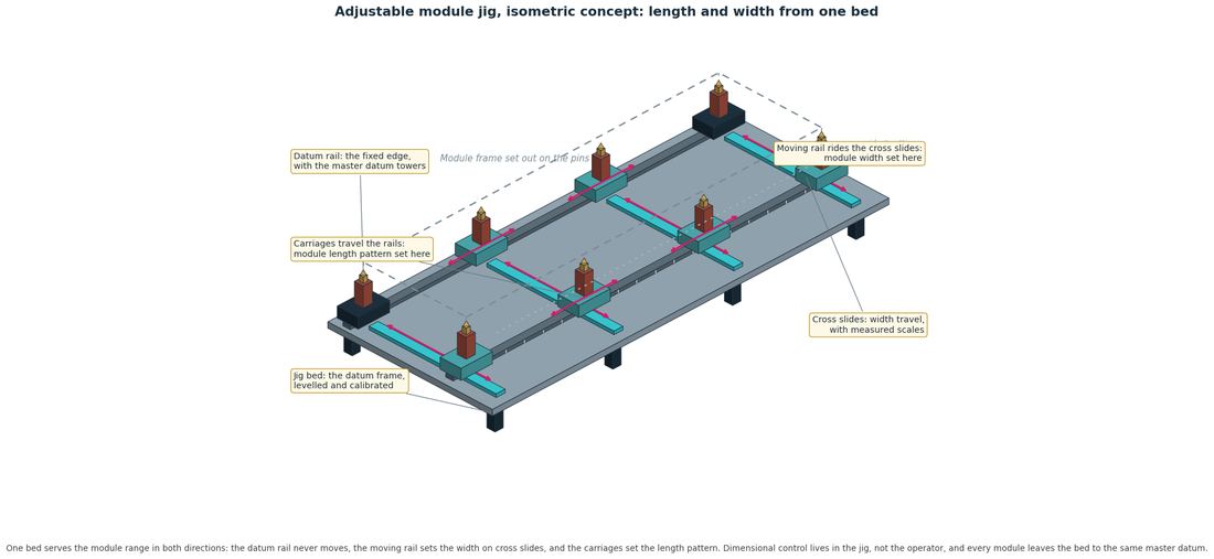
Tolerance across the meeting of four modules is the governing issue at the corner. The recommended approach puts dimensional control in an adjustable factory jig, not the operator; the corner block itself is reviewed for manufacture, with development pointed toward building the connection features into the posts.

Adjustable module jig, isometric concept
The adjustable module jig: a fixed datum rail, a moving rail on cross slides for width, and carriages for the length pattern. One bed serves the module range, and every module leaves it to the same master datum.
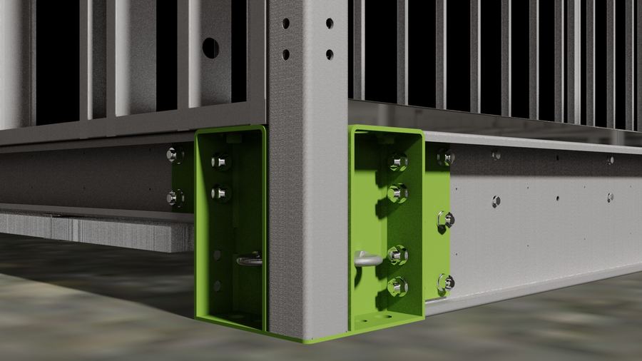
Seismic platform corner connector
Precedent for the folded and welded route: the UK Seismic platform corner connector, adopted prior to significant tooling investment. Image: Seismic Group.

Recommendations and roadmap

The recommended programme from the feasibility report, in three phases.

  • Sobha decisions on the beam arrangement, the floor build up, the vertical post fixing method and the intermediate post arrangement, taken with the options gathered in the companion paper, so that jig design and the twenty storey development start from the right inputs.
  • Sobha architects to overlay the mid span post positions on the apartment layouts and confirm acceptability.
  • Complete the corridor module structural review.
  • Confirm the supply route for any deeper cold formed sections selected for UAE production; the Howick roll former route is identified.
  • Begin Dubai Civil Defence concept engagement with the fire strategy.
  • Confirm site specific wind data and building typology for the first deployment project.
  • Design development to twenty storeys: doubled post provision, deeper bespoke side beam, and the building scale lateral system, developed and calculated for a specific building.
  • Design basis document to Dubai Municipality covering the EN 1993 plus ASCE 7-16 approach.
  • Building scale structural model for the G+20 geometry with concrete core, and formal seismic and tie force checks.
  • Huck fixing review and corner block connection sizing, with evaluation of the ARaymond clip connector as the module to module alternative.
  • Typical details produced through a Sobha and Rethink detail development workgroup, established at the start of the next stage.
  • Appoint a UAE acoustic consultant and freeze the fire and acoustic build ups for testing.
  • Prototype specification: a G+1 or G+2 build, test objectives and pass criteria, with fabrication drawings signed off by the structural engineer before cutting.
  • Book fire and acoustic laboratory slots, with 3 to 6 month lead times, and confirm rig load capability first.
  • Structural test series: stacking, compound beam, corner block and racking tests, with the structural model updated against results.
  • Certification route confirmed with Dubai Municipality or Trakhees, targeting a formal system approval to a stated height.

The full reports

This summary supports the full reports and does not replace them. Download both here.

Concept Feasibility Report

The Stage 2 review in full: the concept as provided, the calculated findings, the route to twenty storeys, connection strategy, fire, acoustics, durability, manufacture, testing and the roadmap. RC/SOBHA/S2/002 V2.4, 40 pages.

Download the Feasibility Report

Development Options companion

The solutions explored during Stage 2, gathered as options: beam arrangements, the floor build up, post options, Huck fixings, the ARaymond connector, the super element approach and the manufacturing route. RC/SOBHA/S2/003 V2.4, 16 pages.

Download the Development Options